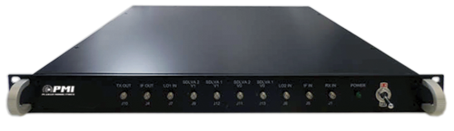
PTRAN-100M18G-70-MAH, Transceiver
PMI Model PTRAN-100M18G-70-MAH is a transceiver covering the frequency range of 0.1 to 18 GHz. This unit up-converts a 0.1 to 4 GHz transmit signal to the 2 to 18 GHz frequency range. It also down-converts a 0.1 to 18 GHz received signal to the 0.1 to 4 GHz intermediate frequency range for analog to digital conversion.
![]()
![]()


![]()
Quick Links: (click the links below for additional information)
Product Feature - PTRAN-100M18G-70-MAH
Product Feature - PTRAN-100M18G-70-MAH Phase 1 Integration
Test Report - PTRAN-100M18G-70-MAH
Test Report - PTRAN-100M18G-70-MAH Phase 1 Integration
Unit Data
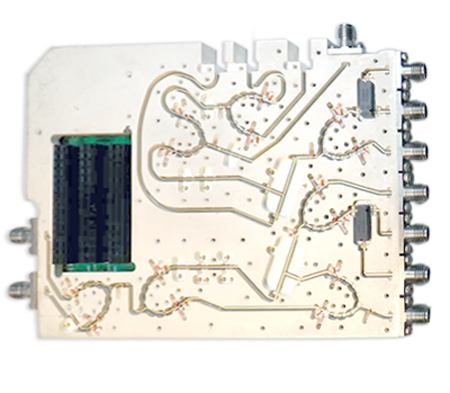
Photos of Transceiver with Filter Banks
Transmit Switch Filter Bank Information:
Model No. 6SFB-100M18G-1MP-MAH-TX
Receive Switch Filter Bank Information:
Model No. 6SFB-100M18G-1MP-MAH
Specifications:
| Frequency | 100 MHz to 18 GHz |
| Inputs | J3, J5, J7, J8 |
| J3 Input | Input from RX Filter Bank |
| Frequency | 0.1 to 18 GHz |
| Power Level | -74 dBm to -4 ± 3 dBm (Assuming 6 dB +/-3.5 dB Gain in RX Filter Bank) |
| J5 Input | IF Input from Backplane |
| Frequency | 0.1 to 4 GHz |
| Power Level | 0 dBm Typ |
| J7 Input | LO1 from Backplane |
| Frequency | 4 GHz to 20 GHz |
| Power Level | 15 dBm Typ |
| J8 Input | LO2 from the Backplane |
| Frequency | 4 to 20 GHz |
| Power Level | 15 dBm Typ |
| Outputs | J2, J4, J6 |
| J2 | Output to TX Filter Bank |
| Frequency | 100 MHz to 18.0 GHz |
| Power Level | Undefined (Allow for 0 to +10 dBm Out of TX Filter Bank) |
| J4 | IF Output to Backplane |
| Frequency | 100 MHz to 4.0 GHz |
| Power Level | 0 dBm typical for Non-Linear SDLVA Channels |
| J6 | Output to RS Filter Bank |
| Frequency | 0.1 to 18 GHz |
| Power Level | Undefined |
| Control Logic | LVDS |
| TTL 1 | SW5 Control - High Frequency or Baseband Channel Select |
| 0 | Baseband Channel (0.1 to 3 GHz) |
| 1 | High Frequency Channel (3 to 18 GHz) |
| TTL 2 | SW7 Control - Linear or Non-Linear SDLVA 2 Channel Select |
| 0 | Non-Linear Channel |
| 1 | Linear Channel |
| TTL 3 | SW12 Control - Linear or Non-Linear SDLVA 1 Channel Select |
| 0 | Non-Linear Channel |
| 1 | Linear Channel |
| TTL 4 | 5 Bit Attenuation Control (1dB Steps) |
| 00000 | 0 dB Attenuation |
| 11111 | 31 dB Attenuation |
| TTL 5 | SW11 Control - Transmit Path Output Select |
| 0 | Output to TX Filter Bank |
| 1 | Output to RX Filter Bank |
| TTL 7 | SW9 and SW10 Control - Baseband or Up-Converted Channel Select |
| 0 | Baseband Channel (100 MHz to 4.0 GHz) |
| 1 | High Frequency Channel (2.0 GHz to 18.0 GHz) |
| TTL X | Lo Select |
| 00 | M1-LO1 M2-LO1 |
| 01 | M1-LO1 M2-LO2 |
| 10 | M1-LO2 M2-LO1 |
| 11 | M1-LO2 M2-LO2 |
| Power Supplies | +12 V, -12 V, +5 V, +3.3 V |
| Size | 5.55" x 3.68" x 0.89" |
| RF Connectors | SMA (F) |
| Digital Connectors | 30 Pin Headers to Connect to inrevium TB-FMCL-PH Board |
| Finish | Painted Gray - Epoxy Polomide Coating IAW MIL-C-22750, Type I over Epoxy Polomide Primer IAW MIL-P-23377, Type I, Class 1 or 3 |
| Operating Temperature | -40 °C to +85 °C |

![]()
![]()

![]()

